


In the pharmaceutical industry, maintaining the highest standards of hygiene and precision is essential. One of the critical aspects of ensuring these standards is the quality of welding used in the construction of piping systems. Orbital welding, particularly when applied to stainless steel tubes, has emerged as a vital technique in this regard. This article explores the significance of orbital welding in the pharmaceutical sector and its advantages when using stainless steel tubes.
*What is Orbital Welding?*
Orbital welding is an automated process that involves rotating the welding arc 360 degrees around a stationary workpiece, such as a pipe or tube. This technique is highly controlled and precise, ensuring uniform and consistent welds. The automation in orbital welding reduces human error and enhances the repeatability of welds, making it particularly suited for applications where high standards of cleanliness and reliability are required.
*Importance in the Pharmaceutical Industry*
In the pharmaceutical industry, the integrity of piping systems is crucial because they transport fluids that are critical to the manufacturing process. Contaminants or imperfections in these systems can compromise product quality and safety. Orbital welding is ideal for this environment due to its ability to produce high-quality, contamination-free welds. This is particularly important in pharmaceutical applications where even the smallest imperfection can affect the efficacy and safety of the products.
*Advantages of Using Stainless Steel Tubes*
1. *Corrosion Resistance:* Stainless steel is known for its excellent resistance to corrosion, which is vital in the pharmaceutical industry where pipes may be exposed to harsh cleaning agents and high temperatures.
2. *Cleanliness and Hygiene:* Stainless steel tubes are non-porous and easy to clean, which helps maintain the required sterility and hygiene standards in pharmaceutical manufacturing environments.
3. *Strength and Durability:* Stainless steel provides the strength and durability needed to withstand high-pressure environments and mechanical stresses, ensuring the long-term reliability of the piping systems.
4. *Ease of Sterilization:* Stainless steel can be easily sterilized, which is crucial for maintaining the cleanliness required in pharmaceutical processes.
*Benefits of Orbital Welding with Stainless Steel*
1. *Precision and Consistency:* Orbital welding ensures a high degree of precision and consistency in welds, which is essential for maintaining the integrity of stainless steel tubes used in pharmaceutical applications.
2. *Minimized Contamination Risk:* The automated nature of orbital welding reduces the risk of contamination, which is critical in environments where cleanliness is paramount.
3. *Enhanced Strength and Durability:* The uniformity of orbital welds contributes to the overall strength and durability of the stainless steel piping, which is crucial for long-term performance.
4. *Reduced Labor Costs:* By automating the welding process, orbital welding can reduce labor costs and increase efficiency, allowing for faster project completion without compromising quality.
*Conclusion*
Orbital welding is a key technology in the pharmaceutical industry, especially when used with stainless steel tubes. Its ability to provide precise, consistent, and contamination-free welds makes it indispensable for maintaining the high standards required in pharmaceutical manufacturing. The combination of orbital welding with the inherent benefits of stainless steel—such as corrosion resistance, cleanliness, and durability—ensures the creation of reliable and effective piping systems crucial for producing safe and high-quality pharmaceutical products.

Surface Roughness (Ra) describes how smooth or rough the inner surface of a component is when it comes into contact with water or product. It is measured in micrometers (µm). The lower the Ra value, the smoother the surface – and the lower the risk of bacteria or biofilm building up.
A rough surface creates the perfect environment for bacteria to attach and form layers of contamination. This makes cleaning more difficult, increases the risk of endotoxins, and may eventually lead to non-compliance with FDA or EMA requirements.
How is the required smoothness achieved?
To meet the hygienic standards, surfaces are usually treated in several steps:
1.Mechanical Polishing: Brings Ra down to about 0.5 µm, but this alone is not sufficient.
2.Electropolishing (EP): A chemical–electrical process that removes a very thin surface layer, eliminates micro-defects, and can reduce Ra to below 0.4 µm.
3.Passivation: A final treatment that removes free iron and builds a protective chromium oxide layer.
Types of Surface Finishes (ASME BPE)
• SF1: Mechanical polish ≤ 0.51 µm Ra – suitable for Purified Water (PW).
• SF4: Mechanical polish + Electropolish ≤ 0.38 µm Ra – the “gold standard” for WFI loops.
• 2B Finish: Factory finish (0.5–0.8 µm) – not acceptable for hygienic systems.
• BA (Bright Annealed): Smoother than 2B (0.3–0.6 µm) but not sufficient on its own.
• Electropolished: Can reach ≤ 0.25 µm – ideal for highly sensitive systems.
It is not limited to piping
Surface roughness is critical not only for pipes but also for:
• Tanks
• Heat exchangers
• Valves
• Instrumentation like flow meters and sampling ports
• Any surface in contact with water or product
In other words: every single component in the loop needs to be checked and documented.
Why is it critical?
Studies such as PDA Technical Report 60 and ISPE Baseline Guide Vol.4 confirm that surfaces rougher than 0.5 µm are hotspots for biofilm growth. Even with advanced CIP/SIP systems, micro-crevices may not be completely cleaned.
How is Surface Roughness verified?
It’s not enough to just specify Ra – it must be measured and proven:
• Contact Profilometers: e.g. Mitutoyo Surftest or Hommelwerke, which use a stylus to measure Ra directly.
• Non-contact Optical Profilometers: laser or white light technologies, used where direct contact is not possible.

When designing distribution loops for Purified Water (PW), Water for Injection (WFI), or Pure Steam (PS), the choice of valve is critical. It often determines whether the system fully complies with FDA requirements or faces validation challenges.
− Valve Types and Hygienic Design
Not all valves are suitable for PW/WFI/PS loops. International guidelines such as ASME BPE and EHEDG define what makes a valve “hygienic”:
• Diaphragm Valves (Two-Way):
Considered the gold standard for PW and WFI systems. They allow full drainability and eliminate dead legs.
• Ball Valves & Butterfly Valves (Conventional):
Contain cavities and dead zones, making them unsuitable for hygienic loops unless designed specifically for pharmaceutical applications.
• Check Valves (Spring-less Design):
Must be spring-free to avoid microbial growth.
− Types of Block T-Valves
• Standard Use Point: single outlet for distribution.
• With Sampling Port: additional outlet for QC sampling.
• With Drain/Return Port: for loop return or point drainage.
− Outlet Design
Key design aspects:
• Required flow rate at the point of use.
• Velocity ≥ 1.0 m/s to prevent biofilm formation.
• Outlet angle < 90° (preferably 45°–60°) to ensure proper drainage.
• Branch length ≤ 1.5D (per ASME BPE).
− Point of Use Cooling
In large pharma facilities, WFI is distributed hot (80–85°C) to maintain microbial control. However, certain applications require cooled WFI (20–25°C):
• Filling machines
• QC laboratories
− Possible solutions:
• Install a POU cooler directly after the Block T-Valve.
• Use an integrated Block T-Valve with cooler.
− Advantages:
• Instant cooling without stagnant zones.
• Space-saving, easy to clean and sterilize (CIP/SIP).
• Better integration into pharmaceutical processes.

- Design temperature of RO membranes
Most membrane manufacturers such as Dow FilmTec, Toray, and Hydranautics test and rate their membranes at 25°C. At this temperature the RO system delivers:
• Maximum salt rejection (typically 99.5%–99.7%).
• Optimum energy consumption.
• Permeate flow according to design.
- Impact of high feed water temperature
When feed water temperature rises above 25°C:
• Water viscosity decreases, leading to higher diffusion of salts and lower rejection.
• Permeate conductivity increases noticeably.
• Above 45°C, polyamide degradation occurs, and the membrane suffers permanent damage.
- Impact of low feed water temperature
During winter, feed water can drop to 18°C or even 10°C:
• Viscosity increases, reducing permeate flow by approx. 3% for every degree below 25°C.
• At 18°C, permeate flow is reduced by around 20%.
• At 10°C, the reduction can reach up to 45%.
• Higher pump pressure is required, which significantly increases energy consumption.
- Can this be compensated with a larger pump?
Yes, it is possible:
• By installing a larger capacity pump.
• Or by using a VFD (Variable Frequency Drive) to increase pump speed.
- However, this is only a temporary solution and has disadvantages:
• Much higher energy consumption.
• Higher risk of fouling and scaling due to increased flow velocities.
• Exceeding the maximum operating pressure can cause permanent membrane damage.
- The ideal solution: Heat Exchanger before the RO
The best approach is to install a Heat Exchanger directly after pre-treatment and before the RO in order to:
• Stabilize feedwater temperature at 25 °C ± 2 °C.
• Maintain the system’s design performance.
• Reduce energy consumption and extend membrane lifetime.
• Prevent problems caused by seasonal temperature variations in the feedwater.

WFI = Water for Injection
, WFI is ultra-pure water specifically produced to be used in the human body through injections.
It must be:
• Free from any microbes
• Completely free from endotoxins
• Free from organic substances that could react with drugs or the body
Uses of WFI:
• Preparing intravenous (IV) or intramuscular (IM) injections
• Cleaning sterilized production equipment
• Preparing sterile drugs or ophthalmic products
• Producing clean steam (for sterilization) • Sometimes used in CIP lines or for preparing certain APIs
How WFI is produced:
Two main methods:
1. Thermal distillation – the traditional, reliable, and most widely used method
2. Membrane systems (RO + UF) – require stricter control and monitoring, less common globally
Most pharmaceutical plants use a Multi-Effect Distiller (MED).
How MED works:
MED works in stages (effects):
1. Feed water (PW or Soft Water) enters the first stage and is heated with plant steam until it boils
2. The pure steam generated is used to heat the next stage
3. Each stage produces more steam, which is condensed at the end to provide ready-to-use WFI
Typical design: 3–7 stages for better energy efficiency and lower steam consumption
Components of each stage:
• Evaporator: to vaporize water and separate impurities
• Separator: to remove droplets or carryover impurities
• Condenser: to convert pure steam back into water
Common operating mistakes and their impact:
1. Unstable feed steam pressure
• reduces distillation efficiency and may fail to remove microbes or endotoxins
2. Ignoring separator check
• tiny droplets may carry impurities into WFI
3. Operating above designed flow rate
• reduces residence time and distillation effectiveness
4. Using a standard condenser without DTS
• risk of contaminated water entering WFI line
5. Running without an effective steam trap
• condensate buildup reduces heat transfer efficiency
6. Skipping periodic sensor calibration (Pressure/Temp/Level)
• false readings may hide operational issues

Rouging is a thin reddish-brown (sometimes black or blue) deposit that forms on the internal surface of stainless-steel piping, especially in Purified Water (PW) and Water for Injection (WFI) loops. It occurs when the protective passive layer on stainless steel becomes damaged or weakened, leading to oxidation of the underlying iron and formation of iron oxides.
Why does it happen more with heat?
1- Hot Water Sanitization (65–80°C):
• In GMP-compliant systems, most companies perform hot water sanitization in the range of 65–80°C, ensuring that the coldest point in the loop reaches at least 60°C for a sufficient holding time to achieve microbial kill.
• This temperature range is microbiologically effective and also reduces the risk of rouging compared to prolonged exposure to higher temperatures.
2- Superheated Water / Pure Steam
• In this case, we are dealing with sterilization at 121°C under pressure, typically used as a shock treatment during emergencies or after a major contamination incident.
• The drawback is that such high temperatures accelerate the formation of tightly adherent black/blue iron oxide layers (Class III – Magnetite), which are difficult to remove.
• For this reason, it is not applied as a routine cycle but reserved for exceptional cases.
Rouging Classes and Their Impact (ASME BPE & WHO GMP):
• Class I: Light discoloration, easily removable, often introduced from other parts of the system.
• Class II: Localized deposits that begin to adhere to the surface.
• Class III: Black or blue oxide, strongly adherent, typically formed under extreme thermal conditions.
Microbial Impact:
As the surface roughens, microbial adhesion increases, making cleaning and sanitization more difficult and raising the likelihood of OOS (Out of Specification) results.
Prevention Measures:
A) Material and Surface Finish
• Use low sulfur 316L stainless steel.
• Apply ASME-BPE compliant surface finishes:
• SF1: Ra ≤ 0.5 µm
• SF4 (Electropolished): Ra ≤ 0.4 µm (smoother, easier to clean).
• Perform chemical passivation after installation or maintenance in accordance with ASTM A967/A380 (nitric or citric acid).
B) Operational Practices
• Maintain hot water sanitization cycles within 65–80°C, ensuring by validation that the coldest point exceeds 60°C.
• Avoid prolonged heating beyond validated ranges.
• Alternate sanitization methods (thermal, thermal shock, qualified chemical) based on risk assessment.
• Maintain proper flow, drainage, and eliminate dead legs.
C) Monitoring and Trending
• Monitor microbiology, conductivity, and TOC.
• Visually inspect welds and hot zones for discoloration. If persistent color appears, initiate de-rouging and re-passivation before progression.
Corrective Actions if Rouging Occurs:
• Class I & II: Chemical de-rouging followed by re-passivation.
• Class III: More difficult to remove; may require advanced chemical treatment and possibly light mechanical polishing.
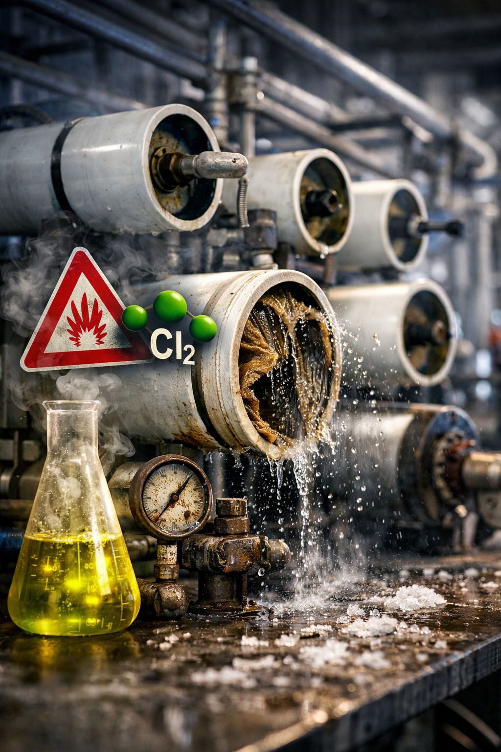
Chlorine: The Most Critical Threat to RO Membranes
Chlorine is often underestimated due to its typically low concentration in water systems. However, it is one of the most harmful substances that reverse osmosis (RO) membranes can be exposed to.
RO membranes are commonly made of polyamide, a material highly sensitive to oxidation. When exposed to chlorine, an oxidative attack occurs, breaking the chemical bonds within the membrane structure. This results in permanent and irreversible damage.
Such damage cannot be corrected through cleaning procedures, including Clean-in-Place (CIP), or any operational adjustments.
Risk Levels by Concentration:
• ≤ 0.01 ppm: Near-zero level; relatively safe for very short exposure only
• 0.02 – 0.05 ppm: بداية gradual, often unnoticed degradation
• 0.1 ppm: Noticeable membrane damage within days
• ≥ 0.5 ppm: Rapid and severe membrane destruction
There is no truly “safe” chlorine concentration over the long term. Exposure time plays a critical role:
• Low concentration over extended periods leads to gradual internal degradation
• High concentration over short periods causes sudden performance failure
One of the key challenges is that chlorine damage is not always immediately visible, but manifests later as unexpected system performance decline.
Typical Indicators of Chlorine Damage:
• Increased permeate conductivity
• Reduced salt rejection
• No visible fouling
• No improvement after CIP
In such cases, the system may appear mechanically sound while suffering from internal chemical degradation.
Warning Signs Requiring Immediate Attention:
• Sudden rise in permeate conductivity
• Performance decline without evidence of fouling
• Inconsistent performance among membranes within the same stage
• Early issues despite relatively new membranes
It is important to distinguish chlorine damage from fouling mechanisms. Chlorine does not cause scaling, biofouling, or organic fouling; instead, it directly damages the membrane structure.
Heat exchangers can be used in high-purity water systems such as PW and WFI, but selecting the right type depends on strict hygienic design requirements and regulatory standards:
- The selection is not only an engineering preference, but a matter of compliance and quality.
- Every component in the loop must prevent contamination and maintain water purity.
- Improper design can lead to serious microbiological and operational risks.
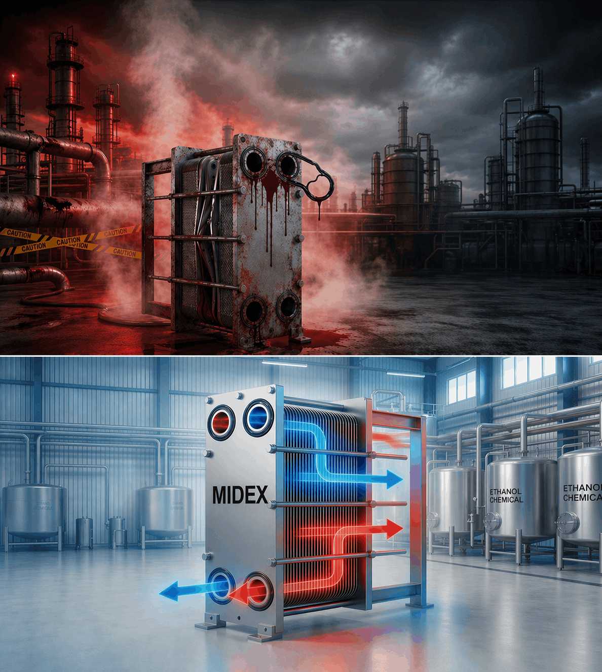
A traditional Plate Heat Exchanger is generally not suitable for these applications due to several design and operational limitations:
- It contains narrow gaps and crevices that may cause water stagnation.
- These areas can promote biofilm formation.
- Effective cleaning and sterilization (CIP/SIP) is difficult for all internal surfaces.
- Some designs cannot withstand thermal shocks during steam sterilization.
- Gaskets may not comply with FDA or USP requirements.
- Risk of extractables and leachables from non-qualified materials.
- Risk of cross-contamination in case of leakage between streams.
In contrast, the Double Plate Hygienic Heat Exchanger is specifically designed for high-purity water systems and offers advanced hygienic features:
- Double plate design with a leak detection zone.
- Any leakage is directed outside the unit instead of mixing fluids.
- Hygienic design ensures full drainability with no stagnant zones.
- Low surface roughness, often electropolished.
- Significantly reduces biofilm formation.
- Materials and gaskets compliant with FDA and USP Class VI.
- High resistance to steam sterilization (SIP).
- Uniform flow distribution with no shadow areas.
- Fully compatible with CIP and SIP processes.
However, Shell & Tube heat exchangers are still widely used in these systems due to their reliability:
- Long proven history in pharmaceutical applications.
- Excellent resistance to thermal shocks.
- Easy steam sterilization (SIP).
- Simple and robust design.
- Suitable for high flow rates.
- Long operational life and easy maintenance.
The Double Plate Hygienic Heat Exchanger also offers important operational advantages:
- Higher heat transfer efficiency than Shell & Tube.
- Faster heating and cooling response.
- Compact footprint suitable for skid systems.
- Lower energy consumption.
- Suitable for precise temperature control applications.
Therefore, a Double Plate Hygienic Heat Exchanger can be used in PW and WFI systems and is often considered best practice, provided that:
- A qualified and reliable pharmaceutical-grade supplier is selected.
- The design complies with hygienic standards (EHEDG / FDA / USP).
- Material quality and internal finishing are ensured.
- The hydraulic design avoids any dead legs or stagnation zones.
- Full compatibility with CIP and SIP is verified.